Saturday, April 18, 2015

Current

Current is a flow of electrical charge carriers, usually electrons or electron-deficient atoms. The common symbol for current is the uppercase letter I. The standard unit is the ampere, symbolized by A. One ampere of current represents one coulomb of electrical charge  moving past a specific point in one second. 


Physicists consider current to flow from relatively positive points to relatively negative points; this is called conventional current or Franklin current. Electrons, the most common charge carriers, are negatively charged. They flow from relatively negative points to relatively positive points.       


Electric current can be either direct or alternating. Direct current (DC) flows in the same direction at all points in time, although the instantaneous magnitude of the current might vary. In an alternating current (AC), the flow of charge carriers reverses direction periodically. 

An example of pure DC is the current produced by an electrochemical cell. The output of a power-supply rectifier, prior to filtering, is an example of pulsating DC. 

An electric current always produces a magnetic field. The stronger the current, the more intense the magnetic field. A pulsating DC, or an AC, characteristically produces an electromagnetic field. This is the principle by which wireless signal propagation occurs.

Voltage

What is voltage?

Voltage should be more correctly called "potential difference". It is actually the electron moving force in electricity  and the potential difference is responsible for the pushing and pulling of electrons or electric current through a circuit.

Sources of electromotive force (EMF) or voltage

To produce a drift of electrons, or electric current, along a wire it is necessary that there be a difference in "pressure" or potential between the two ends of the wire. This potential difference can be produced by connecting a source of electrical potential to the ends of the wire.
There is an excess of electrons at the negative terminal of a battery and a deficiency of electrons at the positive terminal, due to chemical action.

Then it can be seen that a potential difference is the result of the difference in the number of electrons between the terminals. The force or pressure due to a potential difference is termed e.m.f. or voltage.

The greater the voltage, the greater the flow of electrical current (that is, the quantity of charge carriers that pass a fixed point per unit of time) through a conducting or semiconducting medium for a given resistance to the flow. Voltage is symbolized by an uppercase italic letter V or E. The standard unit is the volt, symbolized by a non-italic uppercase letter V. 

Voltage can be direct or alternating. A direct voltage maintains the same polarity at all times. In an alternating voltage, the polarity reverses direction periodically.An example of direct voltage is the potential difference between the terminals of an electrochemical cell. Alternating voltage exists between the terminals of a common utility outlet.


Monday, April 6, 2015

Boolean Algebra with example

These are a few examples of how we can use Boolean Algebra to simplify larger digital logic circuits.

Example 1

Construct a Truth Table for the logical functions at points C, D and Q in the following circuit and rewrite the single logic gate that can be used to replace the whole circuit.
Boolean Example Circuit
 
The circuit consists of a 2-input NAND gate, a 2-input EX-OR gate and finally a 2-input EX-NOR gate at the output(Q). As there are only 2 inputs to the circuit labelled A and B, there can only be 4 possible combinations of the input ( output will be combination of those inputs =22 ). Plotting the logical functions from each gate in tabular form will give us the following truth table for the whole of the logic circuit below.

InputsOutput at
ABCDQ
00100
01111
10111
11001
In this truth table, column C represents the output function generated by the NAND gate, while column D represents the output function from the Ex-OR gate. Both of these two output expressions then become the input  for the Ex-NOR gate.
By looking at the final output at Q we can say, the whole of the above circuit can be replaced by just one single 2-input OR Gate.

Example 2

Find out the Boolean algebra expression for the following circuit.
Boolean Example Circuit No2
 
The system consists of an AND Gate(A.B), a NOR Gate(A+B) and finally an OR Gate(A+B). Both these expressions are also separate inputs to the OR gate. Thus the final output expression is given as:
Boolean Example No2
 
The output of the circuit is given as Q = (A.B) + (A+B), but the notation A+B is the same as the De Morgan´s notation A.B, Then substituting A.B into the output expression gives us a final output notation of Q = (A.B)+(A.B), which is the Boolean notation for an Exclusive-NOR Gate as seen in the previous section.
InputsIntermediatesOutput
BAA.BA + BQ
00011
01000
10000
11101
Then, the whole circuit above can be replaced by just one single Exclusive-NOR Gate and indeed an Exclusive-NOR Gate is made up of these individual gate functions.

Boolean Algebra

Summary of 2-input Logic Gates

The following Truth Table compares the logical functions of the 2-input logic gates above.


The following table gives a list of the common logic functions and their equivalent Boolean notation.

2-input logic gate truth tables are given here as examples of the operation of each logic function, but there are many more logic gates with 3, 4 even 8 individual inputs. The multiple input gates are no different to the simple 2-input gates above, So a 4-input AND gate would still require ALL 4-inputs to be present to produce the required output at F and its larger truth table would reflect that.

Logic Gates

Three main basic types of digital logic gate, the AND Gate, the OR Gate and the NOT Gate. And also  we have seen that each gate has an opposite or complementary form of itself in the form of the NAND Gate, the NOR Gate, and that any of these individual gates can be connected together to form more complex Combination Logic circuits.

In Digital Electronics both the NAND gate and the NOR gate can both be classed as “Universal” gates as they can be used to construct any other gate type. In fact, any combination circuit can be constructed using only two or three input NAND or NOR gates.

Digital Logic Gates can be made from discrete component like ResistorsTransistors andDiodes to form RTL (resistor-transistor logic) or DTL (diode-transistor logic) circuits, but today’s modern digital 74xxx series integrated circuits are manufactured using TTL (transistor-transistor logic) based on NPN bipolar transistor technology or the much faster and low power CMOS based MOSFET transistor logic used in the 74Cxxx, 74HCxxx, 74ACxxx and the 4000 series logic chips.

Standard Logic Gates


Friday, April 3, 2015

Capacitors


Circuit Symbols


Introduction

Capacitors is a simple passive device that is used to “store electricity”. The capacitor is a component which has the ability to store energy in the form of an electrical charge producing a potential difference (Static Voltage) across its plates, much like a small rechargeable battery. 

There are many different kinds of capacitors available from very small capacitor beads used in resonance circuits to large power factor correction capacitors, but they all do the same thing, they store charge. In its basic form, a Capacitor consists of two or more parallel metal plates which are not connected or touching each other, but are electrically separated either by air or by some form of a good insulating material such as waxed paper, mica, ceramic, plastic or some form of a liquid gel as used in electrolytic capacitors. The insulating layer between a capacitors plates is commonly called the Dielectric.

Due to this insulating layer, DC current can not flow through the capacitor as it blocks it allowing instead a voltage to be present across the plates in the form of an electrical charge.


When used in a direct current or DC circuit, a capacitor charges up to its supply voltage but blocks the flow of current through it because the dielectric of a capacitor is non-conductive and basically an insulator. However, when a capacitor is connected to an alternating current or AC circuit, the flow of the current appears to pass straight through the capacitor with little or no resistance.
There are two types of electrical charge, positive charge in the form of Protons and negative charge in the form of Electrons. When a DC voltage is placed across a capacitor, the positive (+ve) charge quickly accumulates on one plate while a corresponding negative (-ve) charge accumulates on the other plate. For every particle of +ve charge that arrives at one plate a charge of the same sign will depart from the -ve plate.
The amount of potential difference present across the capacitor depends upon how much charge was deposited onto the plates by the work being done by the source voltage.


Calculating Charge

By applying a voltage to a capacitor and measuring the charge on the plates, the ratio of the chargeQ to the voltage V will give the capacitance value of the capacitor and is therefore given as: C = Q/Vthis equation can also be re-arranged to give the more familiar formula for the quantity of charge on the plates as: Q = C x V

Standard Units of Capacitance

The capacitance of a capacitor tells you how much charge it can store, more capacitance means more capacity to store charge. The standard unit of capacitance is called the farad, which is abbreviated F.

  • Microfarad  (μF)   1μF = 1/1,000,000 = 0.000001 = 10-6 F
  • Nanofarad  (nF)   1nF = 1/1,000,000,000 = 0.000000001 = 10-9 F
  • Picofarad  (pF)   1pF = 1/1,000,000,000,000 = 0.000000000001 = 10-12 F

Capacitors in Series/Parallel

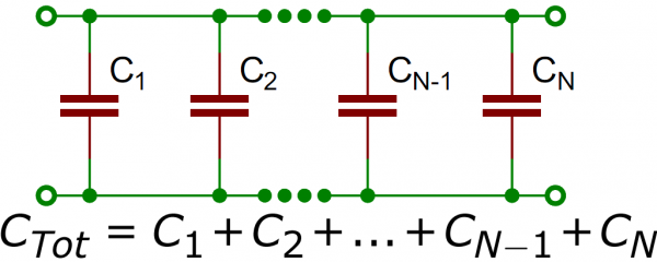
Much like resistors, multiple capacitors can be combined in series or parallel to create a combined equivalent capacitance. Capacitors, however, add together in a way that’s completely the opposite of resistors.

Capacitors in Parallel


Capacitors in Series


Types of capacitors

When deciding on capacitor types there are a handful of factors to consider:
  • Size 
  • Maximum voltage
  • Leakage current
  • Equivalent series resistance (ESR)
  • Tolerance
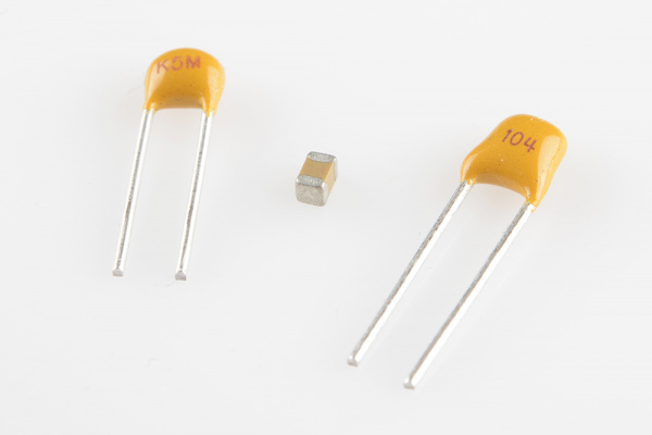
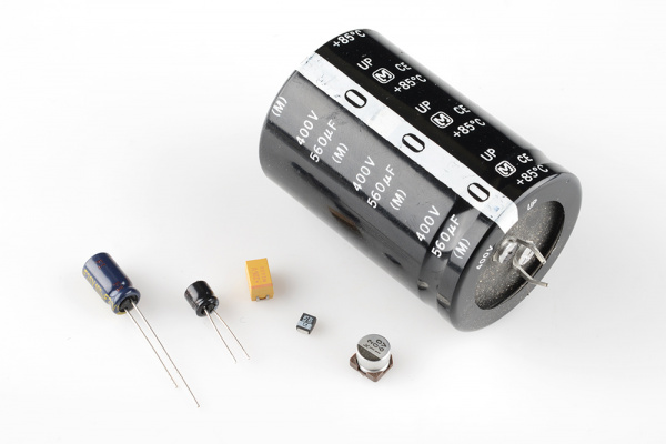
Ceramic Capacitors                       Aluminum and Tantalum Electrolytic                 


Saturday, March 21, 2015

Kirchoff’s Laws

Kirchoff’s Voltage Law

Step 1:- Select one of the loops in the circuit
Step 2:- Choose a direction out of clockwise and anti-clockwise for the loop chosen
Step 3:-Identify the direction of the current component of each branch of the loop
chosen.

Kirchoff’s Current Law


Step1: Select a node.
Step 2:-Identify the currents entering to the node and currents leaving from the node.


Here is the example for Kirchoff's law problem. 

Wednesday, March 18, 2015

Resistors

 Resistors


Resistors, (R) are the most fundamental and commonly used of all the electronic components. There are many different Types of Resistor available for the electronics constructor to choose from, from very small surface mount chip resistors up to large wire-wound power resistors.

The principal job of a resistor within an electrical or electronic circuit is to “resist” or to set the flow of electrons (current) through them by using the type of conductive material from which they are composed. Resistors can also be connected together in two different ways. Those are series and parallel combinations to form resistor networks which can act as voltage droppers or current limiters within a circuit.

Types of resistors


There are thousands of different types of Resistor and are produced in a variety of forms because their particular characteristics and accuracy suit certain areas of application, such as High Stability, High Voltage, High Current etc, or are used as general purpose resistors where their characteristics are less of a problem.

Types of resistors

  •  Carbon resistors

The Carbon Resistor is a low to medium type power resistor which has a low inductance making them ideal for high frequency applications but they can also suffer from noise and stability when hot. Carbon resistors are generally prefixed with a “CR” notation (eg,CR10kΩ ) and are available in E6 ( ± 20% tolerance (accuracy) ), E12 ( ± 10% tolerance) and E24 ( ± 5% tolerance) packages with power ratings from 0.125 or 1/4 of a Watt up to 5 Watts.

  • Film type resistors

The generic term “Film Resistor” consist of Metal Film, Carbon Film and Metal Oxide Film resistor types, which are generally made by depositing pure metals, such as nickel, or an oxide film, such as tin-oxide, onto an insulating ceramic rod or substrate.


  • Wire wound type resistors

Another type of resistor, called a Wire wound Resistor, is made by winding a thin metal alloy wire (Nichrome) or similar wire onto an insulating ceramic former in the form of a spiral helix similar to the film resistor above.

Sunday, March 15, 2015

AC and DC current

Electricity flows in two different ways: either in an alternating current (AC) or in a direct current (DC). Current is nothing but the movement of electrons through a conductor, like a wire. Actually electrons flows in opposite flow of direction to the current.

The difference between AC and DC lies in the direction in which the electrons flow. In DC, the electrons flow steadily in a single direction. In AC electrons keep switching directions, sometimes going "forward" and then going "backward."The best way to transmit electricity over large distances is used alternating current .

Differences  of AC and DC current


Electronics

Everyone today is exposed to electronic devices. The computer revolution is a most famous example.  A study of electronics starts with electricity mainly focusing to AC and DC current and some of the basic electronics components.  And also this includes Ohm's law and other basic principles of electricity .  By referring various books on electronics  you can gain more knowledge of these basic electronics concepts. Let's move on Ohm's law and types of current.

Ohm's law :

Ohm's Law deals with the relationship between voltage(V) and current(I) in an ideal conductor. This relationship states that:
The potential difference (voltage-V) across an ideal conductor is proportional to the current (I)through it.The constant of proportionality is called the "resistance" and it denote by R.
through this definition Ohm's law can be:
    V = I R
where V is the potential difference between two points which include a resistance R. I is the current flowing through the resistance.