Circuit Symbols
Introduction
There are many different kinds of capacitors available from very small capacitor beads used in resonance circuits to large power factor correction capacitors, but they all do the same thing, they store charge. In its basic form, a Capacitor consists of two or more parallel metal plates which are not connected or touching each other, but are electrically separated either by air or by some form of a good insulating material such as waxed paper, mica, ceramic, plastic or some form of a liquid gel as used in electrolytic capacitors. The insulating layer between a capacitors plates is commonly called the Dielectric.
Due to this insulating layer, DC current can not flow through the capacitor as it blocks it allowing instead a voltage to be present across the plates in the form of an electrical charge.
When used in a direct current or DC circuit, a capacitor charges up to its supply voltage but blocks the flow of current through it because the dielectric of a capacitor is non-conductive and basically an insulator. However, when a capacitor is connected to an alternating current or AC circuit, the flow of the current appears to pass straight through the capacitor with little or no resistance.
There are two types of electrical charge, positive charge in the form of Protons and negative charge in the form of Electrons. When a DC voltage is placed across a capacitor, the positive (+ve) charge quickly accumulates on one plate while a corresponding negative (-ve) charge accumulates on the other plate. For every particle of +ve charge that arrives at one plate a charge of the same sign will depart from the -ve plate.
The amount of potential difference present across the capacitor depends upon how much charge was deposited onto the plates by the work being done by the source voltage.
Calculating Charge
By applying a voltage to a capacitor and measuring the charge on the plates, the ratio of the chargeQ to the voltage V will give the capacitance value of the capacitor and is therefore given as: C = Q/Vthis equation can also be re-arranged to give the more familiar formula for the quantity of charge on the plates as: Q = C x V
Standard Units of Capacitance
The capacitance of a capacitor tells you how much charge it can store, more capacitance means more capacity to store charge. The standard unit of capacitance is called the farad, which is abbreviated F.
- Microfarad (μF) 1μF = 1/1,000,000 = 0.000001 = 10-6 F
- Nanofarad (nF) 1nF = 1/1,000,000,000 = 0.000000001 = 10-9 F
- Picofarad (pF) 1pF = 1/1,000,000,000,000 = 0.000000000001 = 10-12 F
Capacitors in Series/Parallel
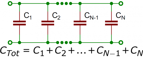
Much like resistors, multiple capacitors can be combined in series or parallel to create a combined equivalent capacitance. Capacitors, however, add together in a way that’s completely the opposite of resistors.Capacitors in Parallel
Capacitors in Series
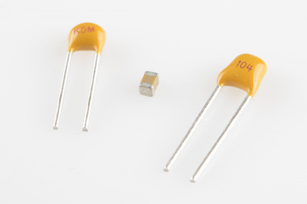
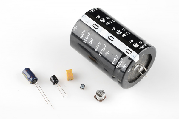
Types of capacitors
When deciding on capacitor types there are a handful of factors to consider:
- Size
- Maximum voltage
- Leakage current
- Equivalent series resistance (ESR)
- Tolerance


No comments:
Post a Comment